IOT prototype: Thermostats display
Table of Contents
Introduction
Nowadays, all buildings have some level of automation for heating/cooling, light control, air conditioning, motion detection, solar panels, etc. Some of these equipments can only be controlled within the house, while other devices can make changes over the internet or publish information to the public cloud.
Our house already has a lot of automation and IT-related networks, including several VLANs and WLANs for different purposes. The central point of home automation is the message broker, which in our case is an MQTT broker. All equipment that is part of the automation is somehow connected to the MQTT broker, either directly or indirectly, such as zigbee2mqtt connecting to the MQTT broker with authenticated credentials. Many devices support various serial communication protocols like Modbus, CAN bus, etc. It is important to understand that automation involves many different manufacturers' devices.
Idea
Every morning I am checking house heating from phone or from laptop. I need to stay with laptop so many hours per day so I just like to verify things from simple display without laptop or phone when i am drinking my morning coffee.
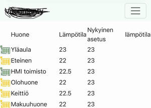

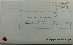
In this first step this display should show only our heating thermostats details and time on UTC (just because ham radio operator always use UTC time). So in first step device need to able fetch MQTT messages from thermostats and parse information from messages and store them locally. To able get some logical order of the rooms one simple idea is just came in from main door and go thouht rooms one by one on clock wise. Other critical thing i need to able look that display without classes.
I have been build electronic more than 30 years so i will make first prototype from equipments what i have already so no new items need to buy for this project.
What need to know/learn?
When embarking on my project, one of the first challenges I faced was selecting a device that would adequately meet my needs. Depending on the application, my goals often included optimizing power consumption, minimizing the PCB footprint, or creating the simplest device possible using existing modules. Sometimes, it’s advantageous to find a device that integrates a set of components, allowing me to focus primarily on the application code.
In my case, I had a large box filled with various microcontroller boards that I had used for prototyping different projects. I explored several options, such as HD44780 controller-based two-row displays, ESP32 microcontrollers, Microchip PIC microcontrollers, and AVRs. However, after some time, I discovered an older ESP8266-based board that featured a small OLED display. This device stood out to me because it required no additional construction beyond creating a box for it with my Bambulab 3D printer.
The next step was to verify the device’s datasheet from the manufacturer. With 4MB of ROM and 80KB of RAM, this board appeared to have more than enough resources for my project, especially when compared to previous projects I had worked on. The ESP8266 and ESP32 have significantly more memory compared to simple AVR or PIC microcontrollers. However, there are many additional features that need to be implemented, all of which consume memory, including the WLAN layer, IPv4 protocol, handling MQTT messages, parsing JSON-based content, and displaying information via an I2C interface to a dot matrix display.
Regardless of the processor family or development board chosen, it is crucial to have a proper SDK for the device. When building an application for a new architecture for the first time, it’s beneficial to start with simple “Hello World” style applications before diving into the specifics of your own project. For the ESP8266 or ESP32 devices, a typical "Hello World" application might involve connecting to an existing WLAN network and/or sending a message through serial communication.
Writing text to a dot matrix display is more challenging than simply writing ASCII text to a serial console. There is no straightforward method to write text directly to the display. My board features a 128x32 dot matrix OLED with an SSD1306 controller connected via the I2C interface. Any command we need to send to the display controller must be encapsulated in I2C messages that are transmitted through the SCL and SDA lines to the SSD1306.
  flowchart LR
 ESP8266<-->|I2C to address Ox3C|SSD1306
 ESP8266<-->|I2C to address Ox2B|SomeOtherDevice
 SSD1306<-->|some set of cables|Dotmatrix
It’s also important to plan how many devices are connected to the I2C bus and the addresses of these devices to ensure that messages are sent correctly. Another challenge is determining the appropriate number of characters that fit on each line, how many lines can be displayed nicely, and how the characters will appear. TrueType fonts look great on a computer, but we need to find a suitable way to render them on a small device while considering size limitations and CPU usage.
To address this, I have chosen to create dot matrix arrays for all the characters I need to use. This information is stored in a C-style header file. Since all characters do not have the same width or height, the structure must also store this information.
Each thermostat in home automation communicates directly or through a gateway to a message broker. To read messages from the MQTT broker, we need to understand MQTT terminology, such as topic, QoS, and payload. Additionally, we must be familiar with the IPv4 stack to understand how devices connect to the MQTT server. Another important aspect is understanding asynchronous tasks and how to subscribe to several topics simultaneously without needing to process all topics. When a message includes multiple pieces of information in a single payload, it should be structured in a way that allows for easy interpretation, such as in JSON format, to facilitate the retrieval of this information.
Simplified diagram of traffic flows:
  flowchart TD
    Thermostat01 <--> |Zigbee|ZigbeeRouter
    ThermostatNN <--> |Zigbee|ZigbeeRouter
    ZigbeeRouter <--> |USB|Zigbee2Mqtt
    Zigbee2Mqtt <-->|MQTT|MQTTBroker
    SolarPanelInverter <-->|Modbus ovet TCP|SolarSoftware
    SolarSoftware --> |MQTT|MQTTBroker
    Switch01 <-->|MQTT|MQTTBroker
    SwitchNN <-->|MQTT|MQTTBroker
    ZigbeeSensors -->|Zigbee|ZigbeeRouter
    ZigbeeLights -->|Zigbee|ZigbeeRouter
    ESP8266Display <--->|MQTT|MQTTBroker
    MQTTBroker <-->|MQTT|LightController
    MQTTBroker <-->|MQTT|MotionController
    MQTTBroker <-->|MQTT|TemperatureController
    LightController<-->WebUI
    MotionController<-->WebUI
    TemperatureController<-->WebUI
Finally, we need to understand how the device is powered and its environmental requirements. A typical USB device is straightforward; it just needs a good quality power supply with 5 volts. However, if I want to power it from a different source, what kind of electrical circuitry is needed? When we have a radio transmitter in the device, we must understand local regulations and how different antennas work. Additionally, when building an enclosure, we need to ensure that there is not too much loss on the radio path.
The building phase
In this case, we just need to build software code to support the board and power unit with 5 volts from a USB cable, so we will concentrate on application development in this chapter. I have selected to use an amd64-based architecture Debian 12 Linux machine for my development environment through an SSH console. I prefer not to install any extra software on my machine; instead, I use containers to build things. If using containers is new to you, just refer to one of my previous posts here.
First, I need to look at my board's datasheet to understand what set of resources we have and how the components are wired to each other, such as which IO pins are connected to the display controller, etc.
  flowchart LR
  subgraph espi2c [esp8266 I2C]
    esda[SDA\npin D2]
    escl[SCL\npin D1]
    erst[RST\npin D0]
  end
  subgraph si2c [ssd1306 I2C]
    ssda[SDA]
    sscl[SCL]
    srst[RST]
  end
  esda <--> ssda
  escl <--> sscl
  erst <--> srst
After that, the more challenging task is how I would like to build the software. I could read all the components datasheets and write all the code myself, which may not be feasible.
Another option is to start finding libraries for my project. PlatformIO is one site that offers several libraries for different purposes. I chose PlatformIO for several reasons:
- PlatformIO supports multiple platforms and frameworks, allowing for easy integration with various hardware, including ESP8266. This flexibility makes it easier to switch between different projects without needing to change development environments.
- PlatformIO provides an extensive library manager, which simplifies the process of finding, installing, and updating libraries. This saves time and effort compared to manually managing dependencies.
- Documentation include my board details
When we build prototype we would like to see some results quickly. That way i like to introduce ESPHome project. This project use under the hood PlatformIO so i know my board is compatible.
Esphome have a nice documentation for all my needs:
- Font Renderer Component
- Global Variables
- Interval Component
- MQTT Client Component
- SNTP Time Source
- SSD1306 OLED Display
- WiFi Component
Esphome configuration is yaml format. In Esphome compile phase PlatformIO configurations are generated. This include reqiured libraries and board information. From yaml file generated cpp file which will be use for next compiling phaces.
Head of yaml config for my device
substitutions:
  platform: esp8266

esphome:
  name: $name

esp8266:
  board: heltec_wifi_kit_8

packages:
  wifi: !include common/wifi.yml
  mqtt: !include common/mqtt.yml

mdns:
  disabled: true

font:
  - file: "font/NotoMono-Regular.ttf"
    id: my_font
    size: 15
    glyphs: '!"%()+=,-_.:°0123456789ABCDEFGHIJKLMNOPQRSTUVWXYZ abcdefghijklmnopqrstuvwxyzäö'

globals:
  - id: thermo_current_heating_setpoint
    type: float[15]
    restore_value: no
    initial_value: '{0,0,...

  - id: thermo_local_temperature
    type: float[15]
    restore_value: no
    initial_value: '{0,0,...

  - id: thermo_on
    type: bool[15]
    restore_value: no
    initial_value: '{false,false,...

  - id: thermo_room
    type: std::array<std::string, 15>
    restore_value: no
    initial_value: '{"","Yläaula","Eteinen",...
Keeping the source code under version control, such as Git, is a good practice, and it is recommended to store credentials in a separate file. This way, other files that contain sensitive information can be excluded from the repository.
Next, we need to discuss how to parse each thermostat's JSON-based payload. When we have 14 thermostats, we just need a few arrays to store different data. To make things a little easier, I am using an array length of 15. This is because my first page displays the time and date.
One thermostat MQTT message handler looks like the following. When I have 14 similar ones, I just use Python code to produce similar things in a loop and copy-paste the results.
mqtt:
 on_json_message:

   - topic: zigbee2mqtt/thermo1
     then:
       - lambda: |-
           if (x.containsKey("current_heating_setpoint"))
             id(thermo_current_heating_setpoint)[1] = x["current_heating_setpoint"];
           if (x.containsKey("local_temperature"))
             id(thermo_local_temperature)[1] = x["local_temperature"];
           if (x.containsKey("heat")) {
             if (strcmp(x["heat"], "ON") == 0) {
               id(thermo_on)[1] = true;
             } else {
               id(thermo_on)[1] = false;
             }
           }
Compiling yaml to elf binary
Each time I modify the YAML file, I need to compile the binary and program the board. As part of the normal development process, this requires a significant amount of time to get everything working on the board as planned.
This is what the end result looks like after compilation.
pashi@dev:~/src/esphome$ podman run --rm -i -t -v $(pwd):/config -v /etc/localtime:/etc/localtime:ro -e USERNAME=root ghcr.io/esphome/esphome:2024.10.2 -s name tdisplay compile tdisplay.yml
INFO ESPHome 2024.10.2
INFO Reading configuration tdisplay.yml...
INFO Detected timezone 'Etc/UTC'
INFO Generating C++ source...
INFO Core config, version or integrations changed, cleaning build files...
INFO Compiling app...
Processing tdisplay (board: heltec_wifi_kit_8; framework: arduino; platform: platformio/espressif8266@4.2.1)
----------------------------------------------------------------------------------------------------------------------------------------------------------
Library Manager: Installing esphome/ESPAsyncTCP-esphome @ 2.0.0
INFO Installing esphome/ESPAsyncTCP-esphome @ 2.0.0
Downloading  [####################################]  100%
Unpacking  [####################################]  100%
Library Manager: ESPAsyncTCP-esphome@2.0.0 has been installed!
INFO ESPAsyncTCP-esphome@2.0.0 has been installed!
Library Manager: Installing heman/AsyncMqttClient-esphome @ 2.0.0
INFO Installing heman/AsyncMqttClient-esphome @ 2.0.0
Downloading  [####################################]  100%
Unpacking  [####################################]  100%
Library Manager: AsyncMqttClient-esphome@2.0.0 has been installed!
INFO AsyncMqttClient-esphome@2.0.0 has been installed!
...
Archiving .pioenvs/tdisplay/libFrameworkArduino.a
Linking .pioenvs/tdisplay/firmware.elf
RAM:   [====      ]  42.4% (used 34756 bytes from 81920 bytes)
Flash: [====      ]  35.2% (used 368037 bytes from 1044464 bytes)
Building .pioenvs/tdisplay/firmware.bin
esp8266_copy_factory_bin([".pioenvs/tdisplay/firmware.bin"], [".pioenvs/tdisplay/firmware.elf"])
esp8266_copy_ota_bin([".pioenvs/tdisplay/firmware.bin"], [".pioenvs/tdisplay/firmware.elf"])
============================================================== [SUCCESS] Took 46.54 seconds ==============================================================
INFO Successfully compiled program.

pashi@dev:~/src/esphome$ wc -l .esphome/build/tdisplay/src/main.cpp
1753 .esphome/build/tdisplay/src/main.cpp
"esphome compile" produced a main.cpp file that has 1753 lines. Later, when I want to build my own improved version of the software, this will give me good hints. The platformio.ini looks as follows:
; Auto generated code by esphome

[common]
lib_deps =
build_flags =
upload_flags =

; ========== AUTO GENERATED CODE BEGIN ===========
[platformio]
description = ESPHome 2024.10.2
[env:pashidisplay]
board = heltec_wifi_kit_8
board_build.flash_mode = dout
board_build.ldscript = eagle.flash.4m.ld
build_flags =
    -DNEW_OOM_ABORT
    -DPIO_FRAMEWORK_ARDUINO_LWIP2_HIGHER_BANDWIDTH_LOW_FLASH
    -DPIO_FRAMEWORK_ARDUINO_LWIP2_LOW_MEMORY
    -DUSE_ARDUINO
    -DUSE_ESP8266
    -DUSE_ESP8266_FRAMEWORK_ARDUINO
    -Wno-nonnull-compare
    -Wno-sign-compare
    -Wno-unused-but-set-variable
    -Wno-unused-variable
    -fno-exceptions
extra_scripts =
    post:post_build.py
framework = arduino
lib_deps =
    esphome/ESPAsyncTCP-esphome@2.0.0
    ESP8266WiFi
    heman/AsyncMqttClient-esphome@2.0.0
    Wire
    bblanchon/ArduinoJson@6.18.5
    ${common.lib_deps}
lib_ldf_mode = off
platform = platformio/espressif8266@4.2.1
platform_packages =
    platformio/framework-arduinoespressif8266@~3.30102.0
; =========== AUTO GENERATED CODE END ============
How big is the end result and what file command tell about the binary:
- 1.8M binary size
- ELF 32-bit LSB executable, Tensilica Xtensa, version 1 (SYSV), statically linked, with debug_info, not stripped
pashi@dev:~/src/esphome$ ls -lah .esphome/build/tdisplay/.pioenvs/tdisplay/firmware.elf
-rwxr-xr-x 1 pashi pashi 1.8M Dec 30 00:23 .esphome/build/tdisplay/.pioenvs/tdisplay/firmware.elf
pashi@dev:~/src/esphome$ file .esphome/build/tdisplay/.pioenvs/tdisplay/firmware.elf
.esphome/build/tdisplay/.pioenvs/tdisplay/firmware.elf: ELF 32-bit LSB executable, Tensilica Xtensa, version 1 (SYSV), statically linked, with debug_info, not stripped
The outcome
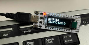
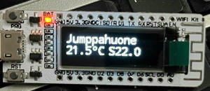
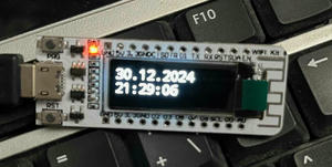
The end result is that we have a device which has 15 different views: one for each room in the house and one for the time and date. The display loops through all views one by one.
After the device boots up, it takes a few seconds before it is able to show proper values. Since I have a time service running locally on our network, this part is fast after the WLAN connection has been initialized. For some thermostat data, we need to wait for a while because they have their own intervals for sending data. During the time when we do not have proper data, we show "Na" in the room details.
The kitchen has reached the heating level, so it is not heating now.
The gym temperature is just below the heating set point, but the thermostat has not yet heated the room.
Time and date.
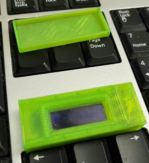
3D printed enclosure.
As a developer, nothing has been ready, and there is always something that could be fine-tuned. Here are some plans for the future of this project:
- Solar panel inverter data
- Bigger display
- Possibility to set the temperature in each room with buttons
- Light status
- The last time a motion sensor was triggered
- Remote controller of Bambulab 3D printer
This post is part of my studies in Business Information Technology at Haaga-Helia.